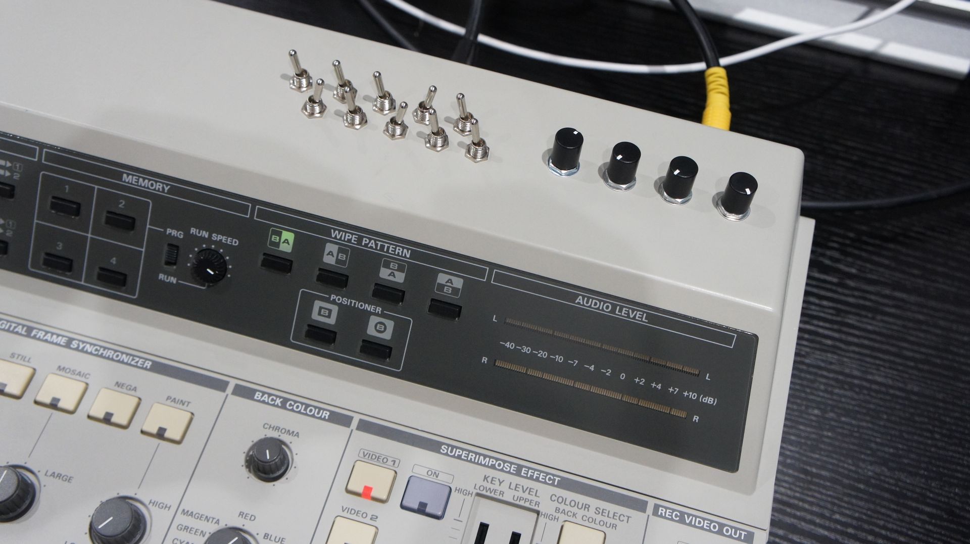
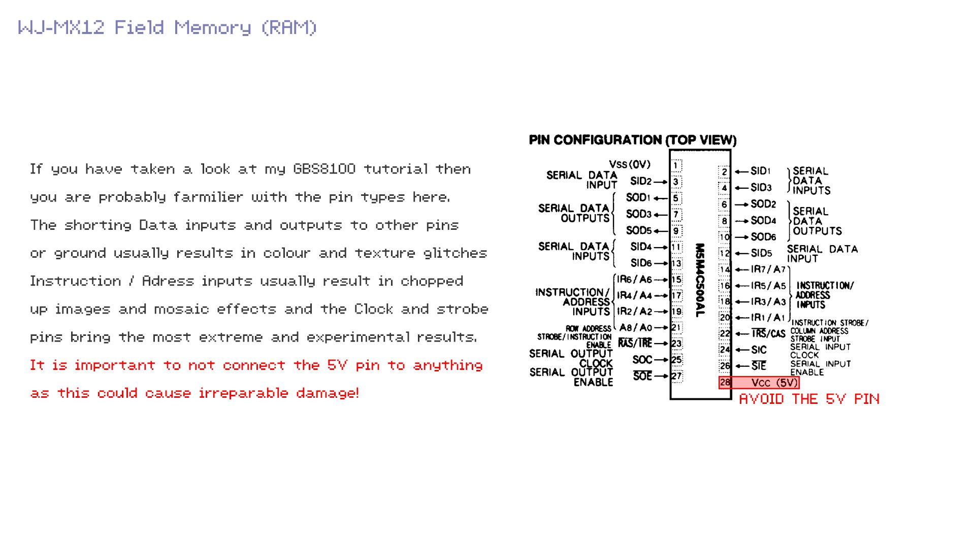
In this guide I will be showing you how to circuit bend the classic MX12 video mixer. Once of my favourite video mixers because of its Digital Frame Synchronizer and how well it plays with glitches. It has a wonderful character when circuit bent thanks to its low resolution digital processing blocks.
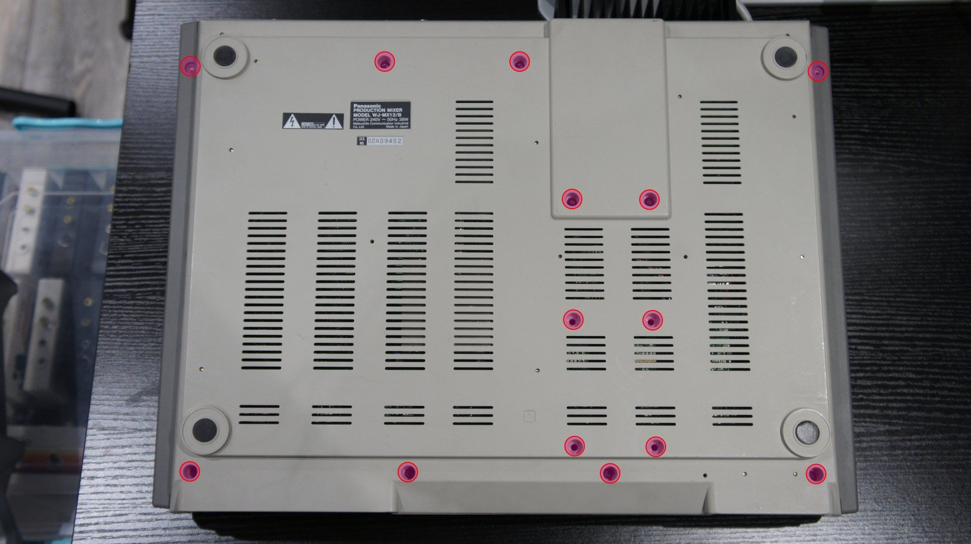
Begin by removing these the screws that are highlighted.
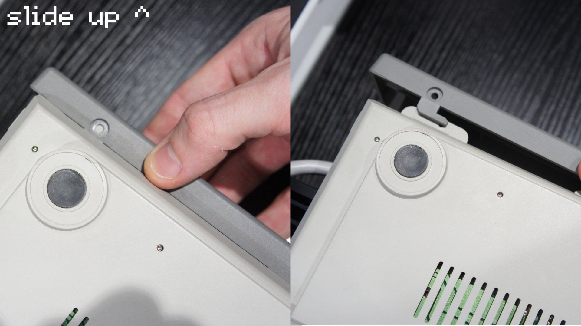
The sides of the MX12 actually hold the two halves of the case together. They need to be slid up and removed to pull the two halves apart.
With the screws and sides removed the MX12 will open up like so:
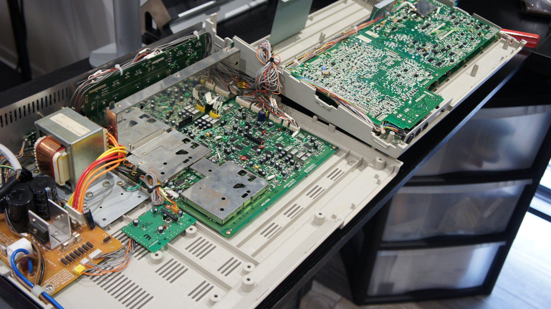
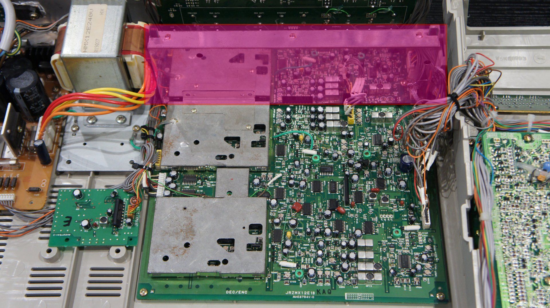
Inside this shiny metal box is our target, the memory card of the MX12. It is inside a metal enclosure to provide robust RF shielding to the circuitry and prevent interference.
To remove it we need to undo two screws, unplug one cable and desolder a ground wire that is soldered to the metal RF sheilding.
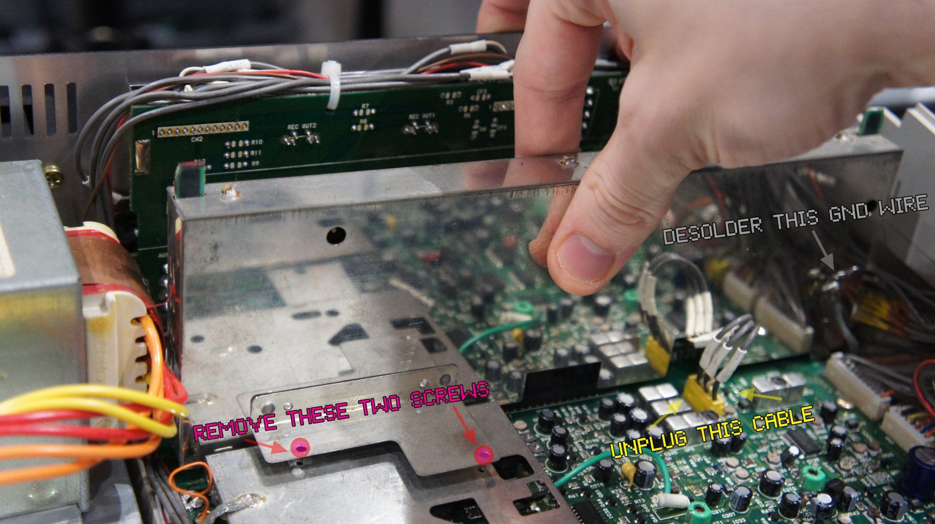
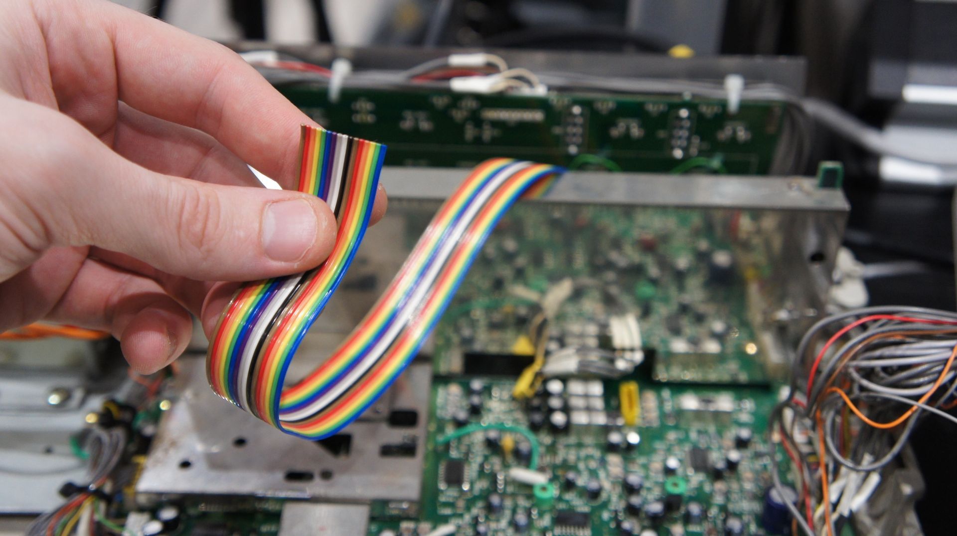
With those 3 things taken care of you can gently lift the whole assembly out. Do so very carefully, making sure you are pulling it out completely vertically so as not to bend the pins in the connector.
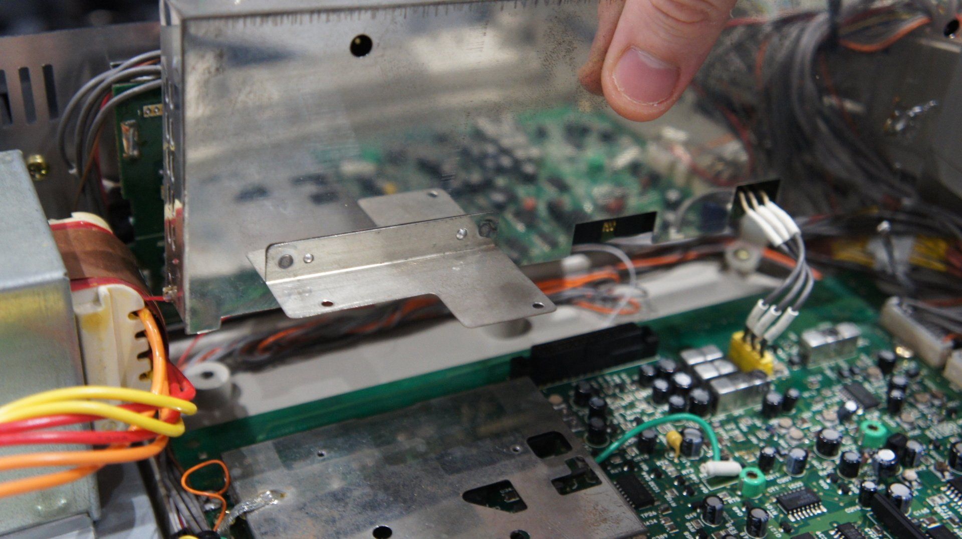
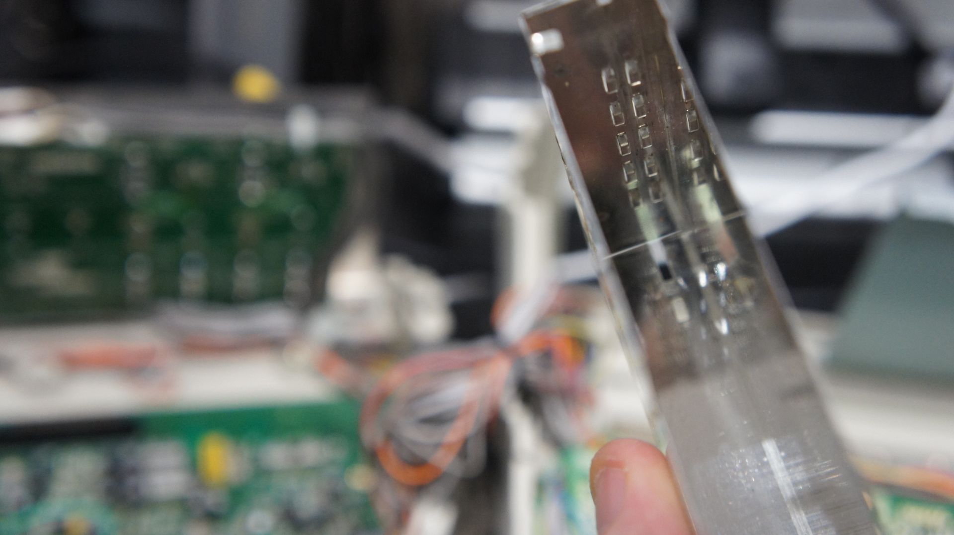
Its Free! Now we can focus on just this little card and ignore the rest of the mixer for now, we wont be touching any other circuitry inside it!
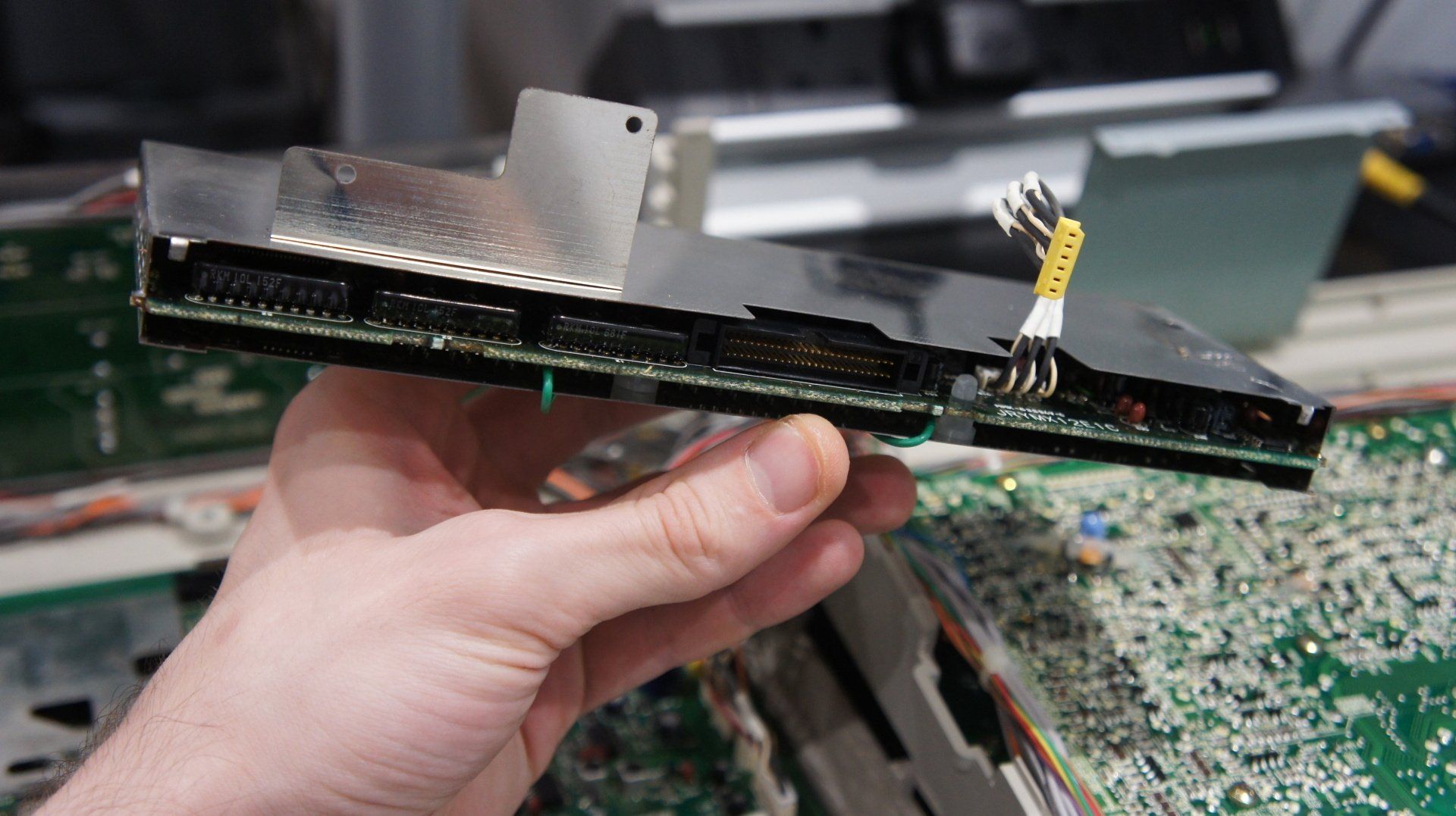
Now we need to remove the shielding on the card. To do this you need to desolder 5 little PCB tabs, 3 located on the top of the card and one near the bottom of either side. I recommend using flux and desoldering braid to remove this.
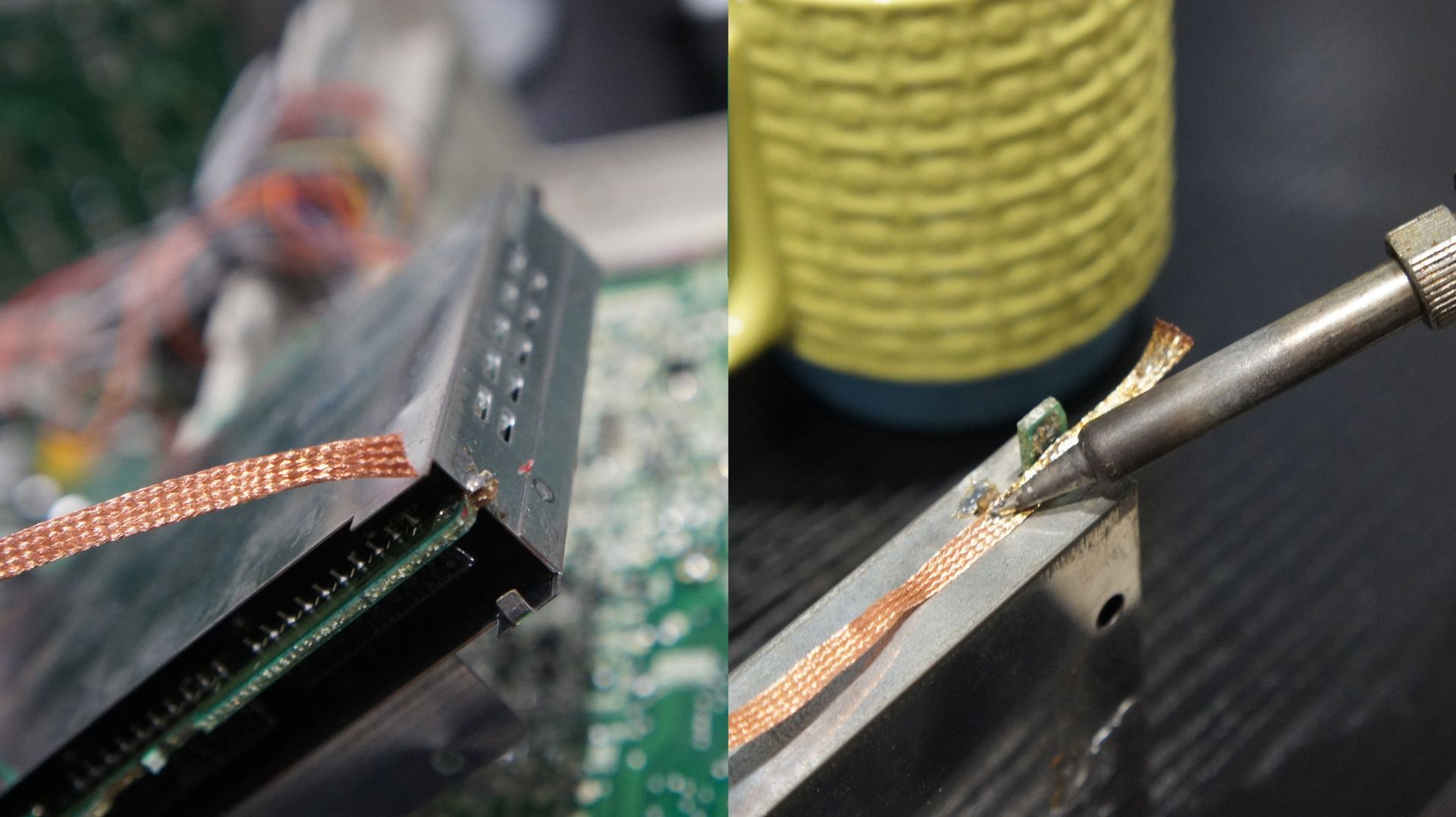
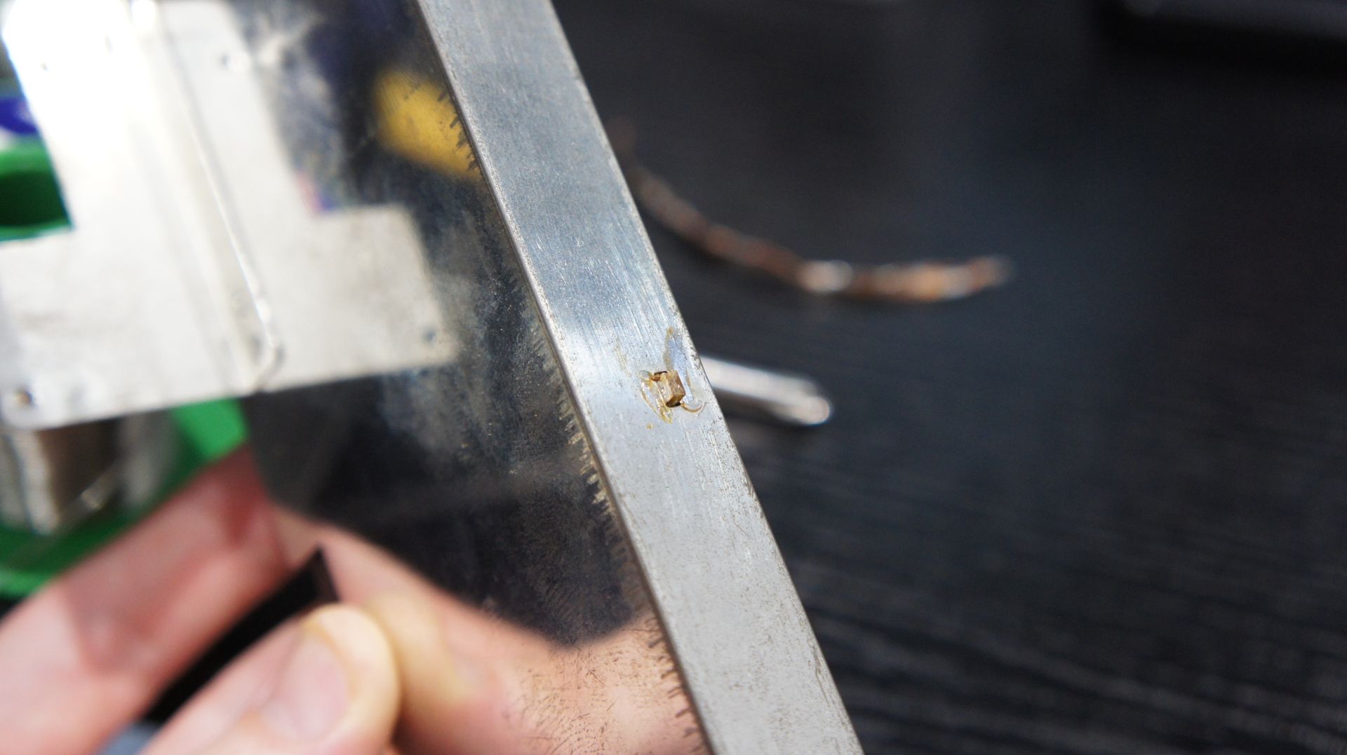
All of the tabs should look like this after solder is removed.
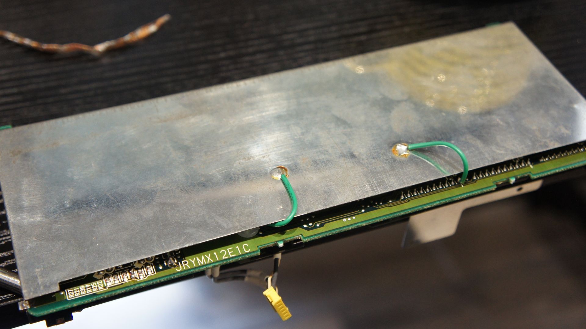
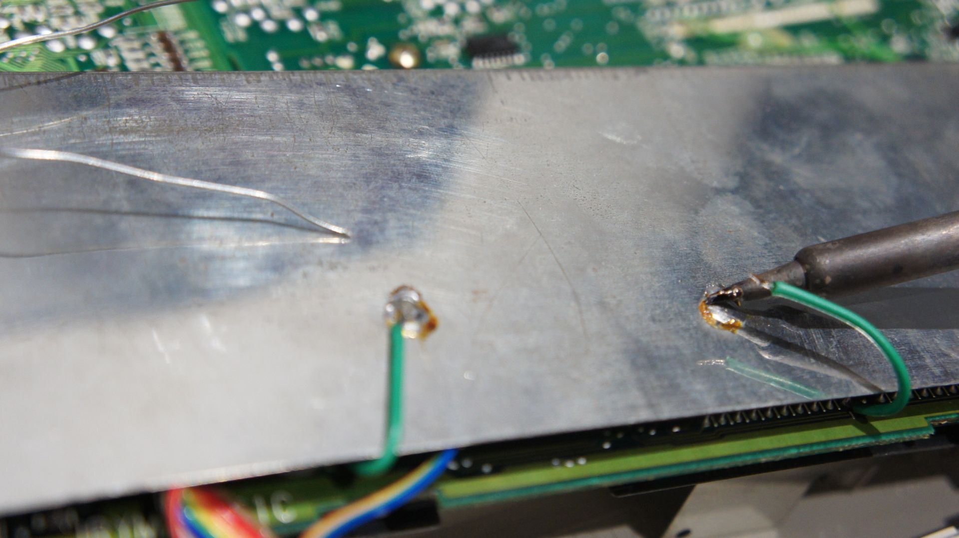
Once last thing before we lift up the casing from the card! Desolder these two green ground wires. Once you have desoldered these two wires you can carefully lift the metal casing from the PCB. The metal case has a channel the PCB slots into, it will have some friction but with some patience you can gently slide the PCB out.
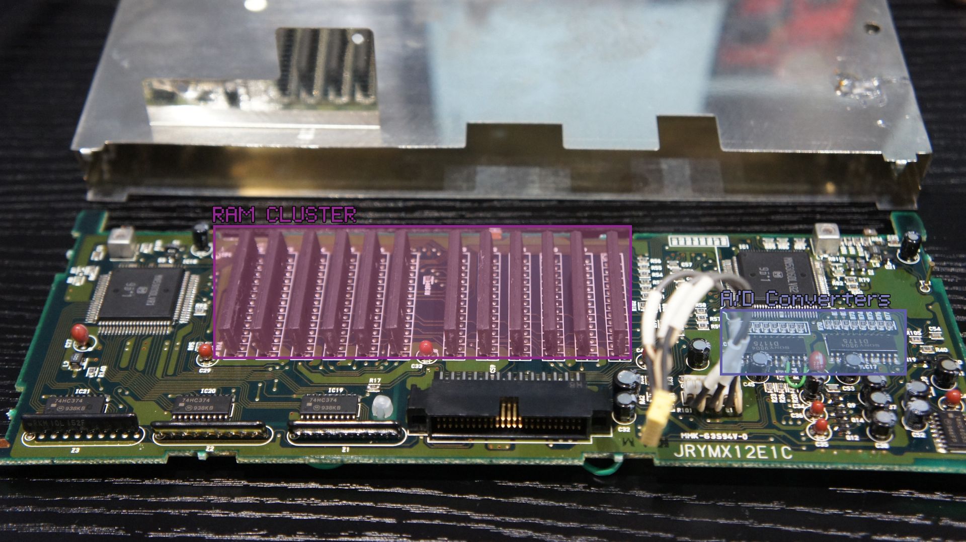
Yay! The memory card is finally free! look at all of those wonderfull vintage integrated circuits! What we want to focus on in particular is highlighted. This includes the RAM chips as well as the Analog to Digital converters. When we carefully cross data lines between all of these parts of the circuit we can get some crazy glitch effects!
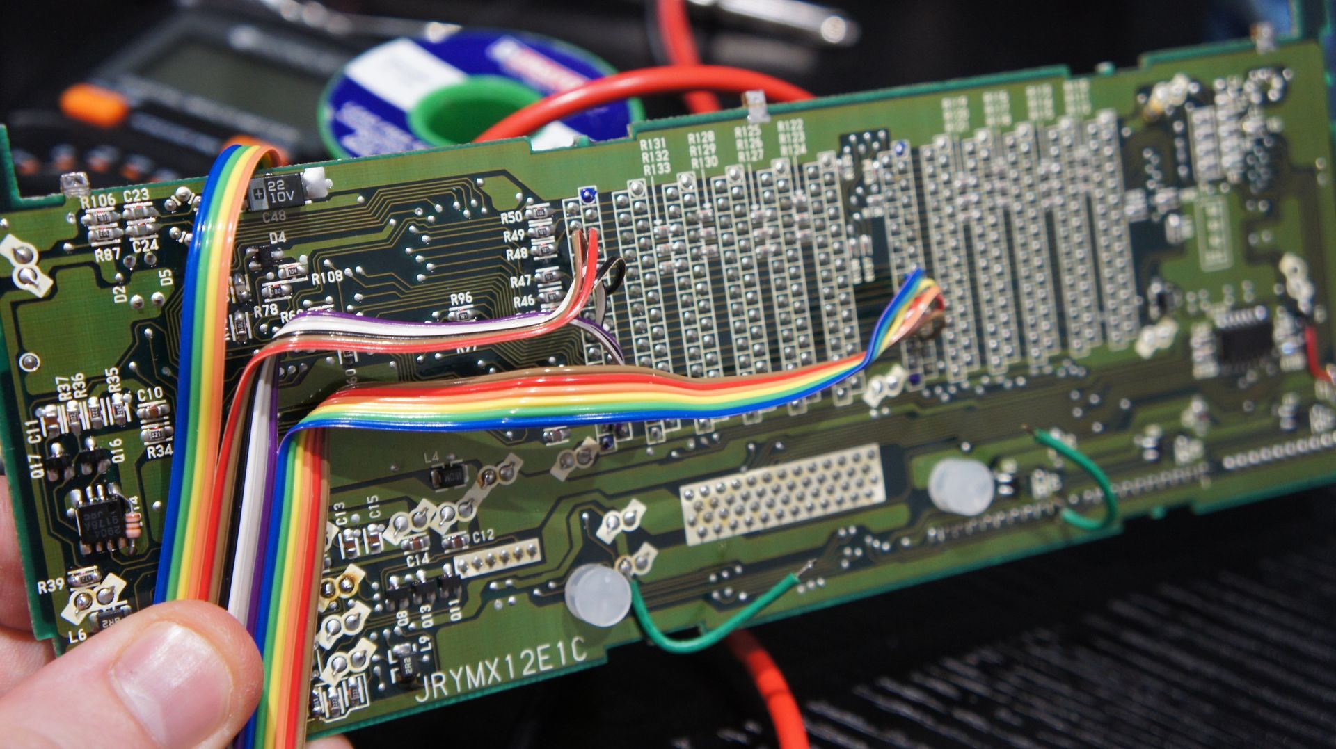
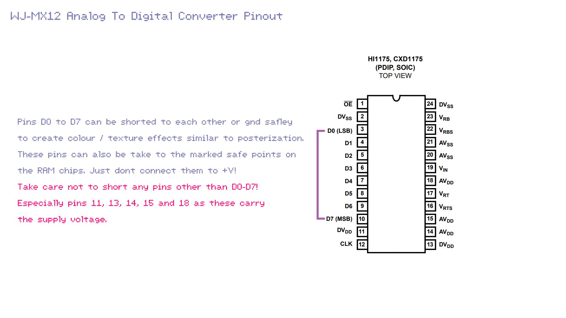
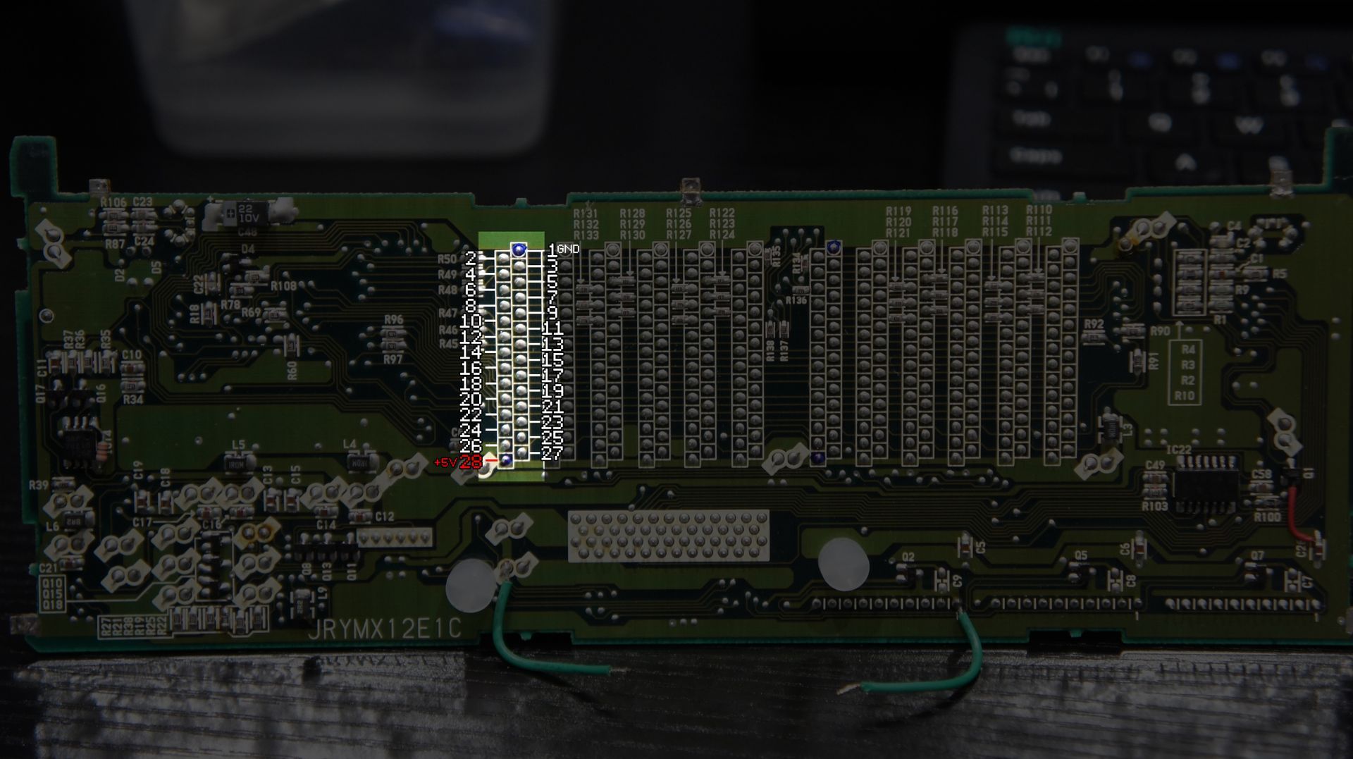
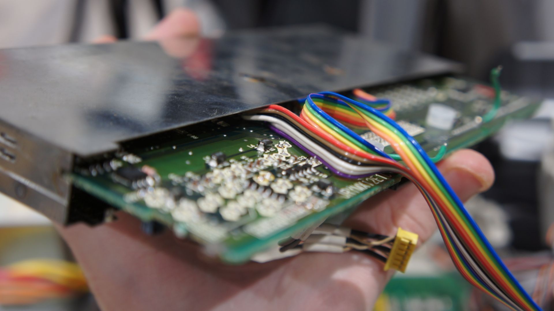
Here is how I soldered mine up. These points run to a bend bus of toggle switches and knobs. Detailed pinouts can be found below to select your own FX point combinations from.
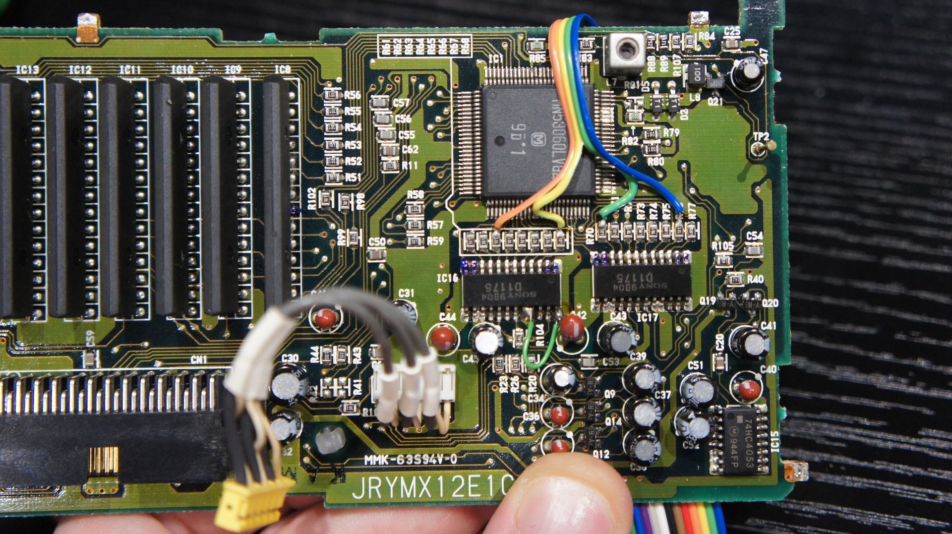
To solder to the points on the A/D converter its easier to solder to the SMD resistors right next to it. You will notice a difference in effect weather you connect before or after these resistors.
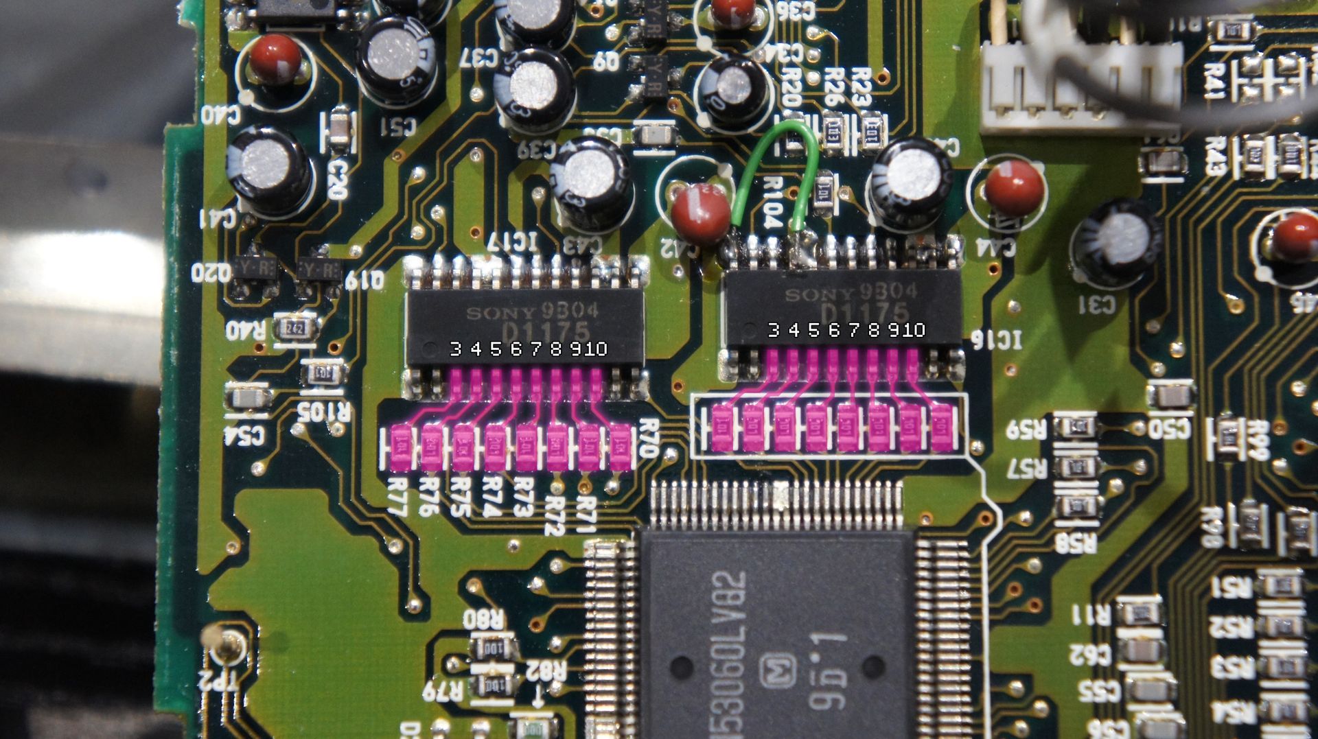
Alot of pins on these RAM chips are connected in parrallel so it makes sense just to focus on one for now. Otherwise you might find yourself soldering in a bunch of wires thinking they are different glitch points only to find out they connect to the same point in the circuit! You can use a multimeter to map out every unique point if you feel like it though!
Once you have soldered in some wires that will connect to our switches and potentiometers, its time to solder the PCB back into its shielding. When doing this take note of the channel in the casing that the PCB will slot into. Gently push the PCB back in making sure not to catch any components on the way in.
Now re-connect these two ground wires and solder the 5 PCB tabs to the case again.
At this point the card can be fitted back into the mixer. We now have a nice set of wires that can be safely shorted to each other witch switches or connected together with pots to get all sorts of nice glitch effects.
The next section will be all about fitting controls to the MX12.
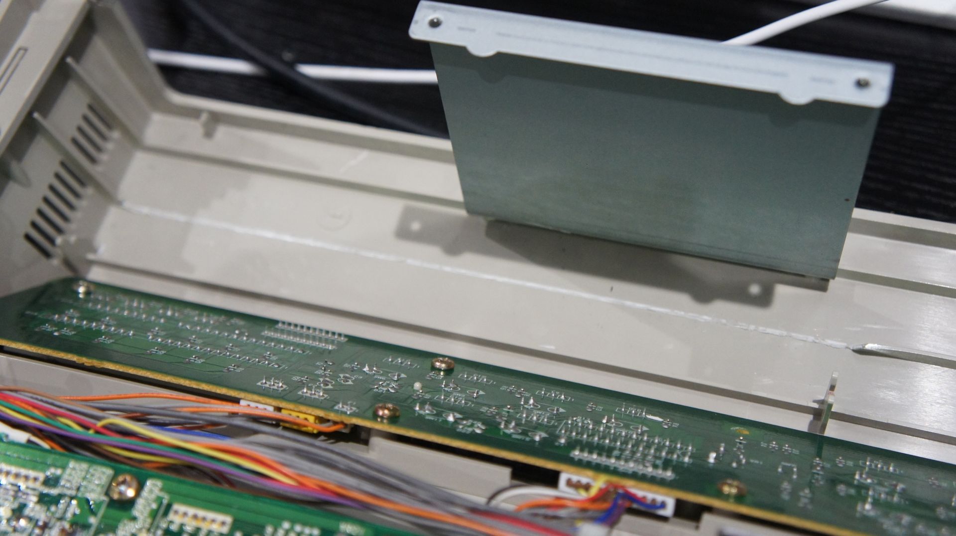
There are a few things to consider when drilling holes on anything to add extra controls. Internal power supply location, reinforcment braces on the inner surface of the plastic, thickness of material etc. The MX12 has tons of room on it but these things need to be considered to utilise it properly.
On an MX12 if you are going to use the top platform for controls I did you will want to avoid the left side where the power supply is and you will likely need to remove the internal support brace with some snips like I did in the picture below.
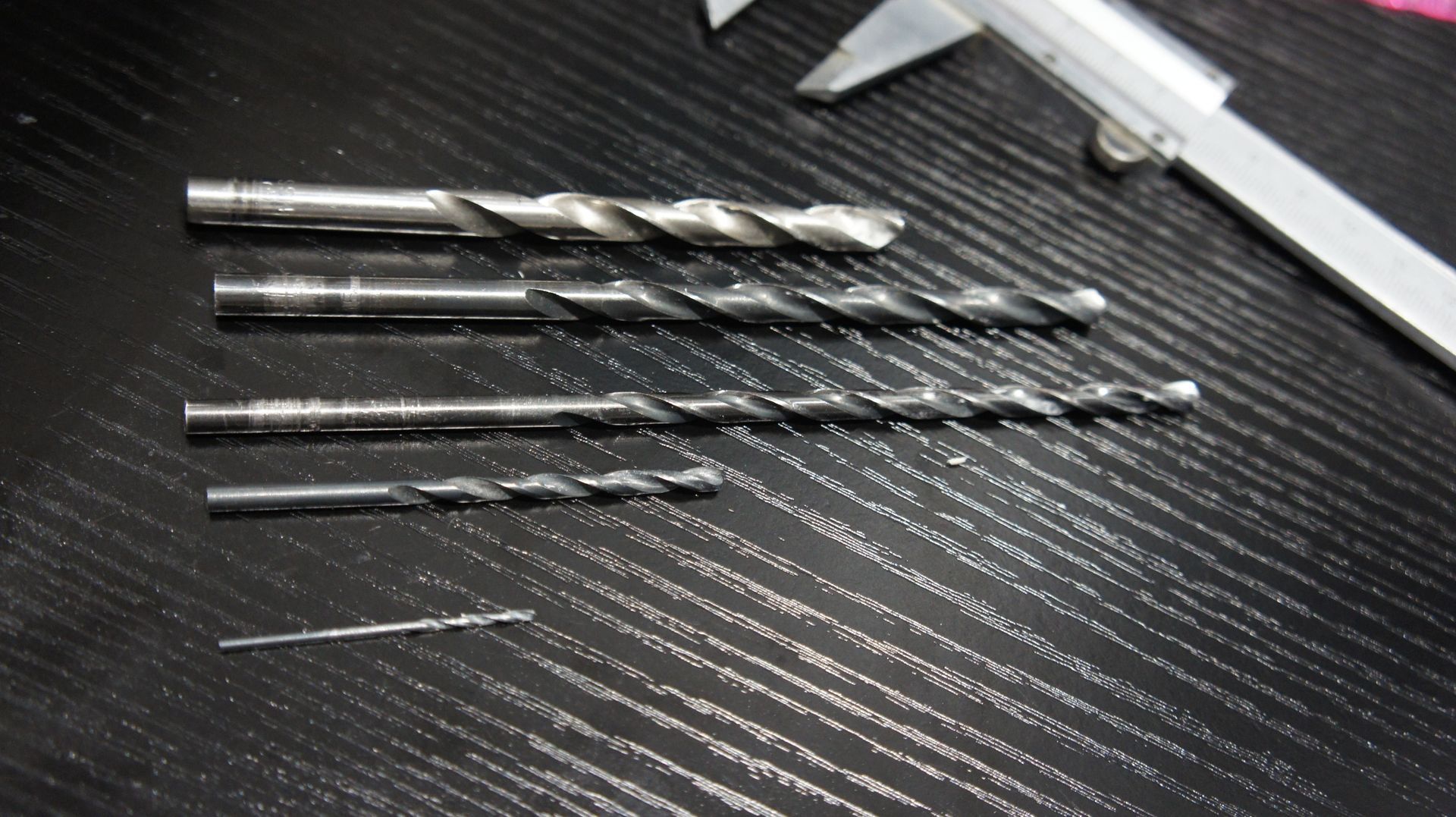
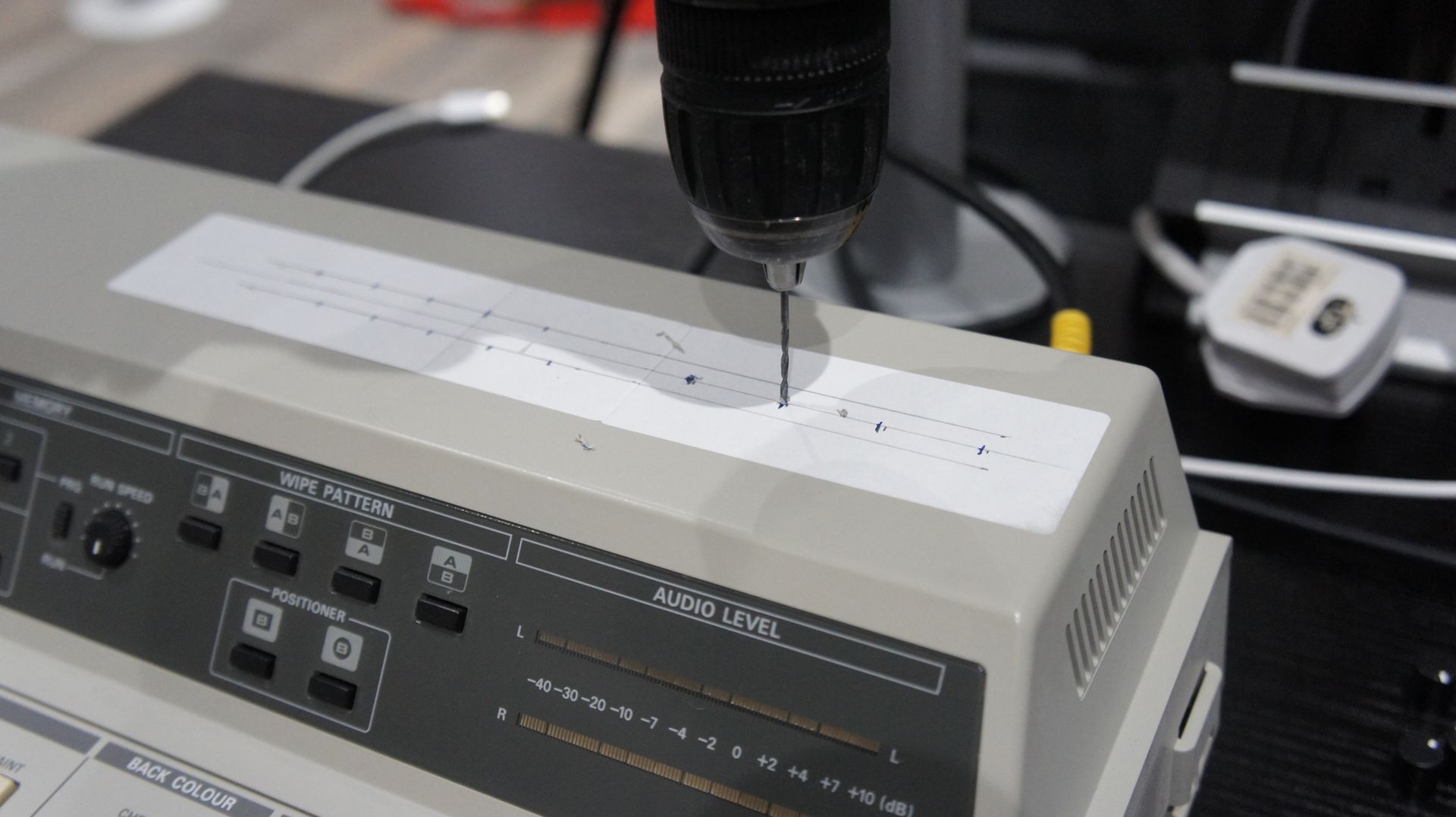
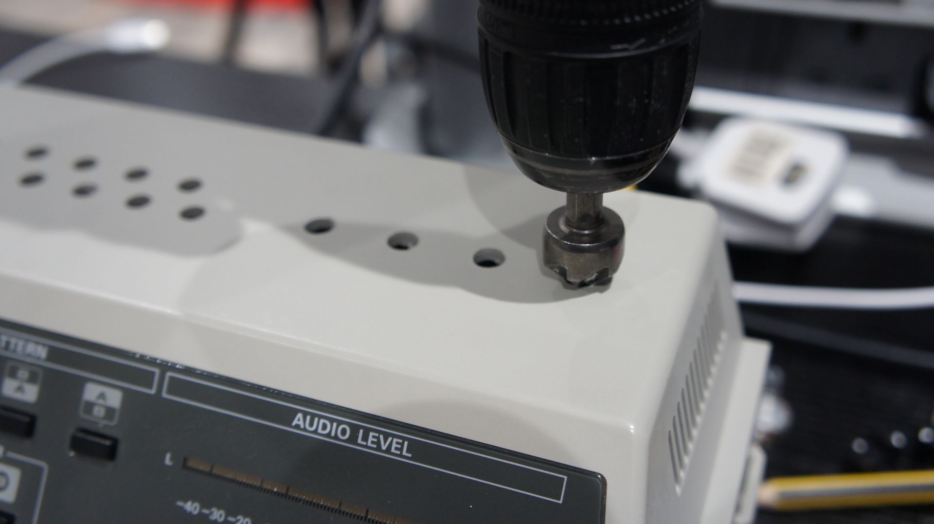
When drilling the holes I recommend using a range of bits from small to the final size. I like to start with 1.5 or 2mm bits to get an accurate pilot hole, then move to a 3.5mm, then to a 6mm etc.
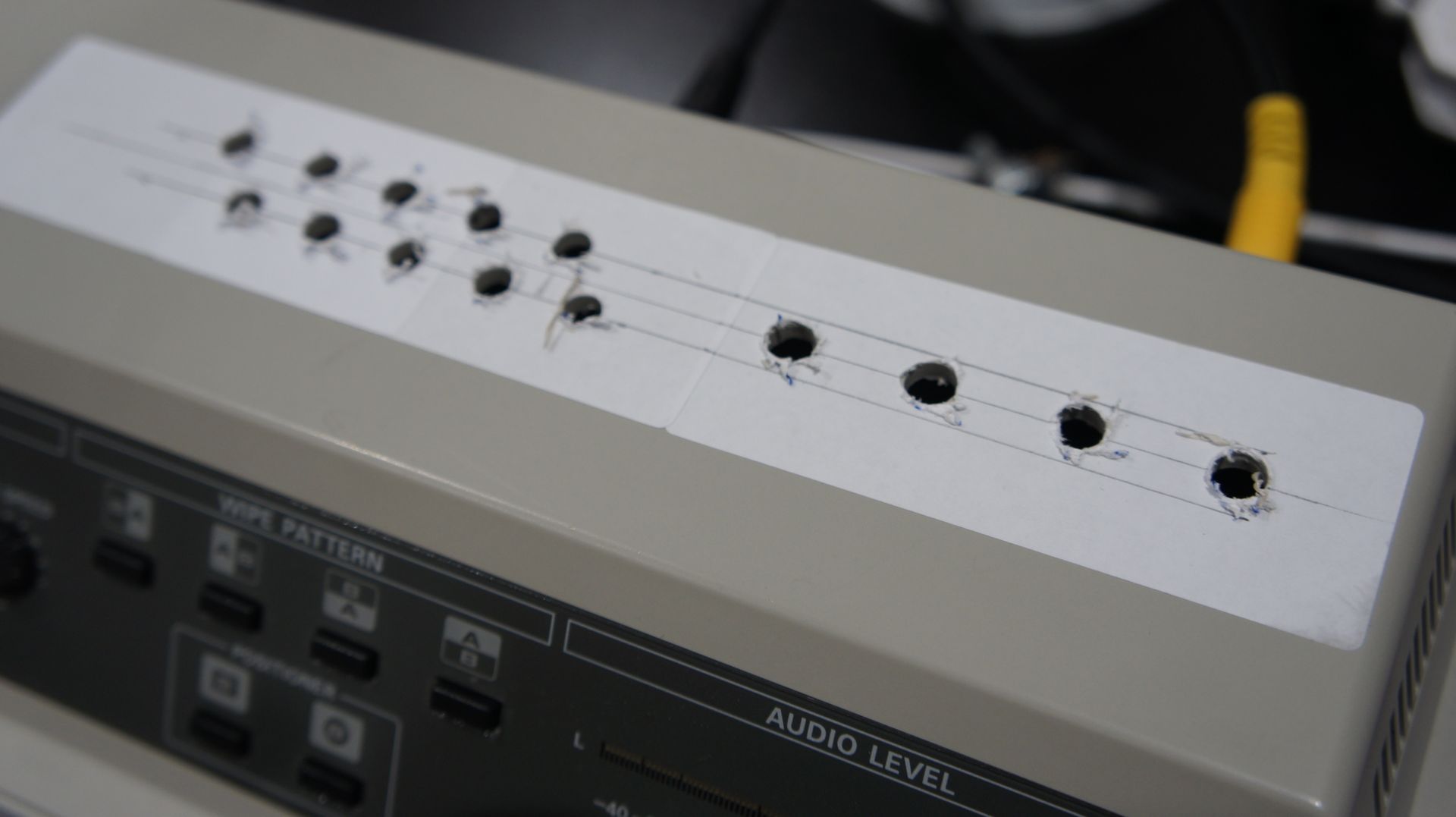
Once all of the holes for the hardware are the correct diameter make sure you deburr the holes. I like to use a countersink but for this, it seems to work particularly well on plastics like this.
Now its time to mount the hardware and wire it in. As you can see in the picture below, I have connected one pin of each switch to a common point and one pin of each pot to a common point to create two effects busses. I then soldered the wires from the memory card to these switches and pots. By flipping switches or turning knobs we create different connection combos of the wires we soldered in. You could have specific hard wired bends if you like (ie two bend points hard wired to one switch) but I like the versatility this gives you.

That's it for this tutorial! Hope you have fun modding your MX12! Tell your friends!